Introduction to the Training Establishments
Resource Management Associates (Pvt) Ltd is a leading energy consultancy company in Sri Lanka which was registered in Sri Lanka in March 1999 with the contribution of Dr. Tilak Siyabalapitiya, Mr. Sunith Fernando and Mr. Upali Daranagama. Now is located at No27, Palmyrah Avenue, Colombo 3.
Mainly it helps this country while giving solutions for energy, environmental and engineering management advisory services to energy supply utilities, industries and commercial institutions. The expertise of RMA ranges from the development to the delivery and utilization of all forms of energy in Sri Lanka and the South Asian region. In their projects, they develop concepts that ensure the optimum utilization of resources in most economical way. Once the project is implemented, they evaluate its performance with respect to energy, engineering and environmental aspects in order to improve resource utilization continuously.
Organizational Structure of RMA
At the moment, Dr.Tilak siyabalapitiya is the Managing director and Mr.sunith fernando works as the company director. Mr. Swetha Perera is the project manager. Organization structure is shown in Figure 1.1
Figure 1.1: Organizational Structure of RMA
Company’s Main Functions
Mainly RMA is providing consultancy services on,
- Power generation – By conducting feasibility studies on thermal power plants and assist the developers in the process of bid preparation, bid evaluation, construction supervision, commissioning and performance testing of power plants for both grid and off-grid applications.
- Renewable energy development – Their services on renewable energy development range from feasibility studies to the analysis of emission credits. They conduct feasibility studies on small hydro, biomass and wind power plants. Their clients in the recent past include Asian Development Bank, Vietnam Electricity/International Copper Association, Sri Lanka Sustainable Energy Authority, Ceylon Electricity Board and potential Sri Lankan investors on wind power generation. In my training period The Renewable Energy Master Plan was developing By RMA for Ceylon Electricity Board.
- Electricity utility planning – They conduct projects on utility distribution systems. Electricity utility planning revolves around the development of cost-effective and environmentally compatible strategies that make it possible to produce, transmit and distribute electricity with high-reliability and at low cost to consumer.
- Energy management & conservation – They provide energy auditing in industries and commercial buildings. They have recently conducted energy efficiency studies for Brandix Garment Factories at RAthmalana. Another task of RMA is planning and implementation of national level energy surveys and development of provincial level energy databases.
- Analysis of energy policies – RMA provides a comprehensive service on energy efficiency, which includes policy analysis, energy auditing and energy efficiency financing.
Strengths of RMA
RMA’s greatest strength is the expertise provided by two of the most experienced engineers in the country, Dr.Tilak Siyambalapitiya and Mr.Sunith Fernando. Clients of the company are assured a reliable service from their past experiences. Another important strength RMA having is they have large network with national and international expert engineers in energy sector, educated people like professors of universities and other key persons in the energy sector. Therefore, RMA continues to remain as a profitable organization.
Weaknesses of RMA
The main weakness is limited number of staff and limited office space. Therefore, they handle limited number of projects at a given time. RMA certainly has the potential to grow into an international consultancy service by enriching its human resources. According to my mind another weakness is advertising and promoting their services is less.
Usefulness to Sri Lankan Society
RMA provides consultancy service to Sri Lankan government in energy sector to get the maximum out of what they spend and it help to the development of the country. Energy sector is a major section of a country. So decisions taken in energy sector affect to the country directly. So, accuracy of energy consulting is very important to develop correct policies and concepts. So, services providing by RMA is very useful to the country.
Suggestions to Improve the company performance
- Increasing the staff to widen the services that can be provided to match the increasing demand for energy consultancy services in the international electricity & energy sector
- Considering about the publicity and marketing the services provided
- Publishing their performances in order to attract more customers or organizations.
Ceylon Electricity Board (CEB)
Introduction of Ceylon Electricity Board (CEB)
Ceylon electricity board is the main organization involved in power generation, transmission and distribution in Sri Lanka. This belongs to the Sri Lankan Government which was established by an act of Parliament in 1969. At present it is controlled under the Ministry of Power and Energy. So this establishment has the responsibility of providing high quality service to its customers while maintaining a reliable, affordable and sustainable electricity supply to the whole Sri Lanka.
Vision and Mission
The Vision
Enrich Life Through Power
The Mission
To develop and maintain an efficient, coordinated and economical system of electricity supply to the whole of Sri Lanka, while adhering to our core values
- Quality
- Service to the nation
- Efficiency and effectiveness
- Commitment
- Safety
- Professionalism
- Sustainability
Main Functions of CEB
- Electricity Generation
- Electricity Transmission
- Electrical Distribution
Electricity Generation
CEB maintain a monopoly in energy market of Sri Lanka. Because CEB is the major power producer in this country and has its own hydro and thermal power plants for electricity generation. And also CEB buys electricity from the Independent Power Producers (IPP). Major hydro complexes are Laxapana Complex, Mahaweli complex and other hydro (Samanalawewa, Kukule, Udawalawe, Inginiyagala, Nilambe). Total hydro power capacity is 1355 MW in Sri Lanka. CEB owns the Kelanitissa Power station (Gas Turbine), Kelanitissa Combined Cycle Plant, Sapugaskanda Diesel Power plant and Norochchole coal power plant which all are thermal power plants. Independent Power Plants are also supporting to the system generating power. At present non-conventional renewable energy generations like wind, small hydro are operating. So, major electricity generation plants are owned by CEB.
Electricity Transmission
Every power system consists of equipment to generate electric energy economically, and with minimum disturbance to the environment. Also most generating plants are located in remote places (Ex: Laxapana, Victoria, Samanalawewa etc.) With respect to the load centers (Colombo, Galle, Jaffna, Kandy) because many of them are Hydro power plant. To deliver this generated energy to the load centers, a transmission system is required. The transmission system should be able to carry this energy reliability, and with minimum loss, at a virtually stable voltage and frequency. Ceylon electricity board electricity transmission network consists of 220 kV and 132 kV transmission lines. In transmission network there are grid substations located over the country. The network is comprised with overhead and underground lines. Most of grids are interconnected and have several lines drawn to improve the reliability of the system. The maintenance, rehabilitation and expansion processes in transmission network are carried out by CEB. Also CEB construct new substations and maintain and operate existing substations. Transmission planning process is another duty done by CEB.
Electricity Distribution
In electricity distribution, major role is done by CEB. Voltages used in distribution system are 33 kV, 11 kV and 400 V. According to the need of the customer CEB provides the relevant supply. Distribution section is responsible for providing customers a quality and reliable power supply and collecting the revenue according to the tariff system proposed by PUCSL. The country is divided in to four regions in distribution. Maintenance of CEB owned distribution network is done by CEB.
Organizational Structure
There are nine Additional General Managers (AGM) and a Finance Manager who are directly responsible to the General Manager. The General Manager is directly responsible to the Chairman and the members of the board. The Secretary to the board, Chief Internal Auditor and the Chief Legal Officer lay in between the General Manager and the Chairman.
The organization structure of CEB is shown below
Figure 1.2: Organization Structure of CEB
Present Performance of CEB
CEB is a non-profitable organization at present. It is running with a loss. It is mainly because of the increase of oil prices at the world market whereas the cost of production of thermal power plants has gone up. Sri Lanka produces considerable electricity energy by using oil. Unit price is fixed according to our tariff scheme. So, there is no way for CEB avoid this huge loss. Due to the huge demand in power and the unreliable conditions of rainfall for reservoirs to produce hydro power tempted CEB to start thermal power plants in Sri Lanka. CEB is looking for using renewable energy to produce electricity which is a good trend.
Strengths of CEB
The human resource is the major strength of the CEB. The skillful and knowledgeable staff carries out a remarkable job of delivering power to the nation from the point of generating to distributing of power. It is a strength that CEB is a state organization so that job security of the employees is guaranteed thereby increasing the job satisfaction. Also, due to government funding CEB own a lot of financial resources and thereby there is no local power producer who can compete with. The customer base is also one of the major strengths of the organization as CEB is wide spread within the country.
Weaknesses of CEB
When we considering the weaknesses, most of the technicians who work lack the knowledge of human safety and the use of safety equipment. It is a weakness of the CEB that proper human safety measures are not followed during work as the human resource is one of their major assets.
It is identified as a limitation of the organization that decisions cannot be made and implemented quickly as they have to go through time consuming government proceedings. As the proceedings of the organization are government regulated, it limits the potential of profit making through adjusting the tariff structure.
Customer care is a sector which CEB performs weak. Immediate attending to breakdowns, providing new connections and revenue collection on time is poor.
Because CEB being a government institute there is lot of political influences happening. Job opportunities, various projects etc. are decided by the politicians not by the educated engineers or executive personnel.
Also the employees’ unions sometimes create problems in this type of places. Not implementing their plans at correct time has created big problems to the country. It is also a weakness. In addition organizational inefficiencies and wastage are other big issues.
Sometimes people take electricity in illegal ways which bring losses to the CEB. But organization doesn’t care more about that because it finally affect to government.
Profitability
In early 90’s CEB was a profit earning institution but now a days it’s very much far from earning any profit. It’s running with losses in millions. This has mainly happened because of providing subsidies for the electricity tariff so that the cost of supply is not charged from a particular group of customers. And also late implementation of plans causes to this situation.
Usefulness to Sri Lankan Society
Electricity is one of the main needs of people as well as the major infrastructure which affects to industrial development. CEB acts more of an organization to fulfill the national need of supplying electricity to the society than a profit oriented organization. Rural electrification is one major evident. Unlike LECO who operates only in the urban areas CEB does a remarkable service to the country. As an employer CEB has already created the best platform for engineering professionals of the country. So it is very important to have reliable power system to a country. So the role of CEB is really important.
Suggestions to Improve the Performance
It is suggested to improve the quality of customer care by monitoring the performance and efficiency of the workers who are to be attending the breakdowns. A program should be implemented to investigate the electricity theft and file lawsuit with the coordination of the police.
Also Correct and suitable plans should be implemented at right time. Maintenance should be carried out regularly to keep the no of breakdowns, failures at a low rate. CEB should be looking forward to use renewable energy resources. Efficiency of organization must increase in order to reduce losses.
Lanka Electricity Company (LECO)
Introduction of Lanka Electricity Company
The Lanka Electricity Company (Pvt) Limited (LECO) was established on September 1983.LECO is the only one company which owns distribution license except CEB in Sri Lanka. Its main business is to buy electrical energy from CEB and sells to end consumers. For this LECO develops, improves, maintains and expands their distribution network to reach the customers. There are seven branch offices accordingly in the regions which its services are offered. They are, Negombo, Kelaniya, Kotte, Nugegoda, Kalutara, Moratuwa and Galle.
Vision of LECO
Enjoy being the light for lives of people through innovative eco-friendly business.
Mission of LECO
To provide the best energy solutions to the society through continuous innovati
Organizational Structure
Figure 1.3: Organization Structure of LECO
Main Functions of LECO
The main functions of the LECO are the associated services of the 11 kV and 400 V distribution network of electricity and collection of revenue from the customers. They are,
- Purchasing electrical energy from the CEB
- Maintain the distribution network and the quality of the supplied electricity
- Provide new connections
- Energy meter testing
- Metering, billing and collection of revenue
- Disconnection and reconnection
Present Performance
LECO has widely spread distribution network and trying to give a reliable service to customers. Also company has own transformer workshop, meter testing lab and training center. Company has now started manufacturing energy meters with the commencement of Ante LECO Metering Company. In addition they are now replacing old analog meters with digital energy meters which can be read remotely. First time in Sri Lanka LECO has introduced the Net Metering system in Sri Lanka, which is now available for customers. They can earn profits by selling energy to country.
Strengths of LECO
The major strengths of the company are the customer base it has and the staff. Electricity distribution is a monopoly market. Therefore, for the electricity consumers within the areas that LECO caters its services, it is a must to purchase electricity form LECO. Since these areas are urban, the customer base is dense. So each distribution transformer can be utilized to serve a lot of customers up to its maximum capacity level which reduces the no load loss of the transformers. Also most of the customers of these urban areas are high end domestic users which bring a lot of revenue to LECO being one of the major strengths of LECO. The staff is one of the most valuable assets of the company. Their sound decision making, expertise of engineering, novelty of services, maintenance of strong customer relationship and satisfaction is made possible as a result of their remarkable workforce.
Weaknesses of LECO
The major limitation faced by the LECO is that its services are restricted into a particular area. So after saturation of the market there will be no room felt for further expansion. Another limitation is that the LECO is being dependent on the power purchased from CEB. So due to faults of the CEB transmission, outages can occur which results in power cuts for LECO customers as well.
1.3.9 Opportunities for Improvements of LECO
At the present market there is room for Independent Power Producers (IPP). Therefore LECO has the opportunity in investing in power generation projects to expand their area of business. LECO has the opportunity to effectively manage the street lighting system in order to minimize the electricity used for street lighting through programs such as using LED street lamps and timer based switching for street lights to avoid them been used during day time. Also improve the revenue collection and adjust to the requirement of PUCSL are another opportunities that can help to LECO development.
1.3.10 Threats for LECO
Electricity theft in the highly urbanized areas creates losses for the company. This is a threat for the company’s profit. Increasing of tariff persuades the consumers to consume less electricity and some customers to electricity theft.
1.3.11 Suggestions to Improve the Performance
According to my mind LECO distribution network should be expanded to other areas also. Company has that potential to cater more customers in a satisfactory way. They should look for other businesses relevant to energy sector by doing electricity distribution. Also a proper resource management is required.
1.3.12 Usefulness to the Country
Being a main competitor for the CEB distribution divisions, LECO has uplifted the standards of customer satisfaction setting an example for their main competitor. Providing reliable power while maintaining the quality, responding to breakdowns immediately and reducing the losses during the distribution are major achievements of LECO which benefits the society. As an employer, LECO has expanded the job market of the country for technical and non-technical personnel while offering their employees with a lot of benefits and job security.
Training Experiences
Resource Management Associates (Pvt) Ltd
My training started on 20th of October 2014, the very first day of my training I reported to Resource Management Associates (Pvt) Ltd at Kollupitiya . There were three undergraduate trainees from our university including me. We spent 12 weeks at RMA.
First day, Project engineers Isuru Dassanayake and Supun de silva gave us a brief introduction about training guidelines for in plant trainees in RMA and what projects are going on at that time.
After first meeting with Dr. Tilak Siyambalapitya , we were assigned to projects.During my 3 months training period I could give my contribution for several project. Of them mainly I were assigned for these projects.
- Maris Stella Branch School Project
- Energy Audit – Brandix Rathmalana.
- Electrical installation design for Church at Negombo.
Maris Stella Branch School Project
Maris Stella College had decided to build new branch school. They had planned to complete it in two phases. In first phase they construct grade 1-11 class rooms, Administration building, main hall etc. In second phase they have planned to construct advanced level section and playground etc. The buildings blocks of the school was named as block ABC, block DEF, block GH, block JKL and block M.
Resource Management Associates (RMA) had been given the honorary task of carrying out the Electrical Engineering aspects of this project. But, without being limited to the scope of Electrical Consultancy, RMA had been coordinating the other professionals so as to make the project successful as quickly as possible.
In my training period at RMA, school was under construction. In this period electrical installation test for block A,B,C,D,E,F,G,H,P and Q were carried out by me. I involved in these works and other minor works such as update drawing according to the final inspections, coordinating with technicians for electrical equipment replacing etc.
2.1.1.1Measurement of earth electrode resistance
Here, we actually measure the resistance to a remote earth from an electrode. There are several methods for measuring the earth electrode resistance as given in IEEE 81.
- Two point method (Ammeter-Volt-meter-Method)
- Three point method
- Ratio method
- Staged fault test
- Fall of potential method
The three point method is the method that is commonly used. Theoretically the earth electrode that is to be tested should be disconnected from other electrodes and the respective installation. Then the tester should be connected to the electrode and other two stakes as shown in Figure 2.1. Distances between inner stake and the earth electrode and minimum distance between two stakes should be 10m. A known current is generated in the path completed by the earth electrode and the outer stake and measures the fall of potential between inner stake and the earth electrode. The tester calculates the resistance by using ohms law (V=IR) gives the earth electrode resistance directly.
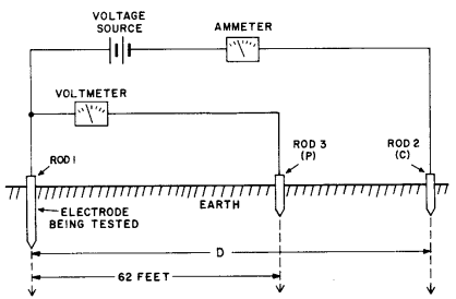
Figure 2.1 Arrangement of Electrodes and stakes.
At the site we used electronic megger which replace voltmeter, ammeter and voltage source and use three pole method. Here we connected the earth rod to the building reinforcement. Because the building columns act as parallel rods and minimized the total electrode resistance. The use megger type was AVO megger and model was DET5/4D.
Many times we found resistance is much higher because of
- Resistances of joints were much higher
- Connection with reinforcement was poor
- Rod have break inside the soil
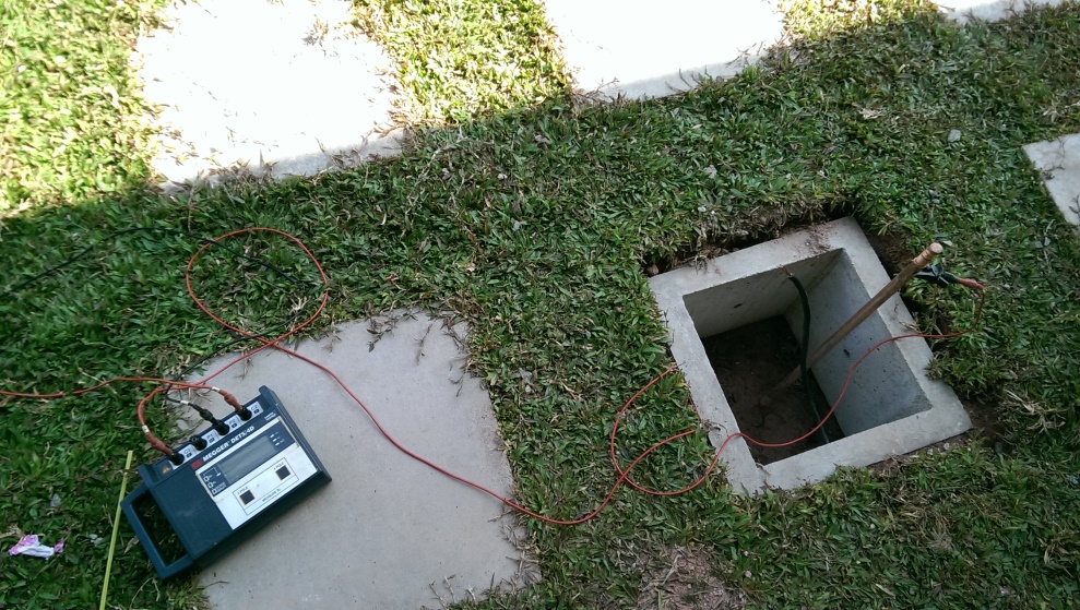
Figure 2.2. Earth rod with Electronic Megger
Solution for the problems that we faced ware,
- Used Pb soldering for every joint with reinforcement to rod.
- Recommended the exothermic welding for rod and conductor joints
- Add another rod parallel with existing rod.
The report should prepared after the every testing and the sample report has added to the ANNEX 1
2.1.1.2 RCD (Residual Current Device) devices testing
RCD devices could be tested using a special device called RCD tester. We create an artificial earth fault with a defined leakage current and measure the time taken trip off the RCD. This test gives us a better idea about functionality of the specific RCD.RCD type was Kioritsu and model 5402D.
The steps that we followed to test the RCCB were,
1. First select the RCCB rating. Ex: 30mA (by Rated Trip).
2. Then select NO TRIP. Here RCD generate ½ rated current through the device .Ex: 15mA for 30mA RCCB.IF RCCB is not faulty one, RCCB no operate.
3. Then select TRIP position and RCD device generate exact 30mA current. If RCCB is faulty It will trip during 2000ms time period.
4. Then select FAST TRIP position and RDC device generate 250mA through the device. At that current RCCB should trip during the 40ms time period
Energy Audit at Brandix Rathmalana
2.1.2.1 Introduction to Brandix Group of Companies.
Brandix Group of Companies include Brandix Asia, Brandix Apparel, Brandix Apparel Solutions Ltd, Brandix Apparel India, Brandix Casualwear Bangladesh Ltd, Brandix Textiles, Brandix i3 and Brandix College of Clothing Technology. Brandix is a growing business spreading its factories and offices across South Asia. It is the single largest apparel exporter in Sri Lanka contributing to the national economy by earning foreign exchange. The company has more than thirty five factories located in Sri Lanka, India and Bangladesh with over 42,000 employees. Brandix manufactures casual wear, sportswear, lingerie and fabrics in their own facilities.
The participants in the audit were from University of Moratuwa, RMA Energy Consultants and Brandix. We conducted an initial walk-through in the factory to be familiar with the processes and the energy converting equipment. After that we were divided into four groups, with each group focused on a particular area, namely,
- Company energy management system and accounting.
- Electricity supply and use
- Thermal energy supply and use
- Air conditioning system
I could joined with the team 2 which was focused on Electricity supply and use and observed and gave the recommendations while analyzing the electricity demand on trans formers and generators.
2.1.2.2 Energy Requirement for Production Line
As a garment manufacture Brandix finishing Ltd.has a higher energy requirement by way of steam and electricity. Energy is primarily used for washing, dyeing, drying and activities involved with finishing a garment. The steam requirement for the above facility is served from a biomass boiler, while backup furnace oil boilers are also available in the facility to use during any failure of the biomass boiler.
Electricity supply from the national grid (from LECO) is used as the primary source whereas a diesel powered generator is available as a backup and main electricity intensive activities are sandblasting, whiskering, permanent creasing, laser blasting and operation of machinery.
At the past furnace oil was used to generate steam. A biomass fueled boiler was installed in April 2013 to generate steam, which has significantly reduced the use of furnace oil
2.1.2.3 Electricity supply and use
There are two electricity supplies from LECO (Lanka Electricity Company) via two dedicated transformers, rated at 1000 kVA and 630 kVA, placed separately in the premises. Each transformer serves the factory through a separate main distribution board (MDB). In addition to that, two standby generators of 1000 kVA and 380 kVA are each connected to the relevant MDBs through a manual changeover switch to serve the load in the event of a mains power failure. Automatic power factor correction capacitor banks are connected to the LV side of the transformer to achieve the maximum power factor.
In the case of a power failure, each standby generator is manually started and connected to the serve the load.The capacitor banks maintain the power factor in between 0.98 -0.99 (=1) with utility power supply from two transformers. It is very important to maintain this figure within that range as much as possible to avoid high maximum demand charge.
There are no updated power line diagrams of the distribution boards in this premise, making troubleshooting, maintenance, system upgrades as well as energy saving programs difficult. Electricity consumption is measured by energy meters placed at transformers. Billing is done according to the Industrial (I2) tariff, which is a time-of-use tariff (peak, off-peak & day). The average monthly electrical energy use is 301 MWh, and the average maximum demand are about 548 kVA for transformer 1 and 239 kVA for transformer 2.
Figure 2.3 – Single Line Diagram for Electrical Distribution of Transformer 1
400A
33/0.4kV
400A
TF1
1000kVA
33/0.4kV
GEN1
1000kVA
0.4kV
Changeover
800A
33/0.4kV
800A
250A
250A
250A
33/0.4kV
125A
33/0.4kV
New Tonello machine room
Dryer
Compressor
Sample new building
Plant
Tonello 20-21
Tonello 24-25
Boiler
400A
250A
TF1
630kVA
33/0.4kV
GEN1
380kVA
0.4kV
Changeover 1000A
1000kVA
33/0.4kV
250A
100A
80A
60A
Laser Room
Waste water purifier
Office area
Figure 2.4 – Single Line Diagram for Electrical Distribution of Transformer 2
Figure 2.5- Load Profile of both Transformer 1 and Transformer 2 for 11th December 2014
According to the combined load profile of both transformers, it can be seen that loads do not significantly vary throughout the day. An early morning valley can be identified. From 9:00 to 18:00, a higher electricity demand is observed. There is some reduction in energy demand in peak time, which can be reduced further down. There are no significant power spikes any time in the day. Maximum demand is achieved in the morning hours each day.
A significant amount of energy cost could be saved by properly analyzing and shifting production plan to fill valleys and smoothening the load curve. Power factor of both transformers is acceptable as automatic power factor capacitor banks are installed.
2.1.2.4 Load Management
There are nearly 29 machines which operate according to a pre-defined production plan. The main focus of machine operation plan is to achieve production targets within the given time periods. Machines consume a significant portion of power used in the factory. Other loads such as lighting, AC (split type), computers and pump loads etc. also exist in the plant, but are not significant as the machines.
2.1.2.5 Observation on Load Curve and Load Management
Energy use is approximately equally distributed to the peak, off-peak and day time slots. The Company prepares the production plan to get the maximum output within a given duration. They stated that they never consider about peak, off-peak or day time when preparing the machine operation plan.
2.1.2.6 Standby Generators
Two standby generators provided emergency power supply to factory during utility power failures. These generators, 1000 kVA & 380 kVA are catering to the total load when a power failure occurs. However, one generator cannot meet the installed transformer capacity, but is capable of serving the present demand.
While considering the monthly diesel consumption of standby generators from June 2013 to June 2014 is shown in the Figure 2.12.
Figure 2.6 – Diesel Consumption of Standby Generators
Figure 2.7 – Monthly Running hours of the Standby Generators
Power interruptions have not affected this factory significantly. Production processes are not highly sensitivity to power interruptions.
2.1.2.7 Energy Management in the Lighting System
Productivity of workers increases with comfortable working environment and sufficient lighting conditions. In this factory, most areas have a sufficient lighting level, while a few areas require improvement. When selecting lamp or luminaire for particular area following facts must be considered
- Efficacy
- Power consumption,
- Color rendering index (CRI)
2.1.2.8 Lighting Distribution
According to the building code task lighting is provided in this premise for sample checking areas where a lighting level of more than 1000 lux is required. A dedicated lighting system is provided in production areas where machines are installed. The lights are switched on only along with the machines. Lighting in certain areas is poor, which causes discomfort to workers. It could be overcome by adding daylight into the working areas. Most of the lights in the facility are energy efficient.
2.1.2.9 Recommendations
Recommendation 1:
Prepare production plans to minimize machine operation in the peak-time and try to shift them to early morning.
Recommendation 2:
Conduct a feasibility study to examine the potential of going with a single account under I-3 tariff, instead of the two separate connections.
Recommendation 3:
Upgrade the single line diagram of each distribution board and attach them to relevant distribution boards.
Recommendation 4:
Prepare and initiate predictive maintenance of the electrical installation.
Recommendation 5:
Maintain standard luminance level in the factory.
Recommendation 6:
Clean the lamp fittings, wall fans periodically.
Recommendation 7:
Conduct a survey to collect data on lighting devices in the factory.
2.1.3 Electrical Layout Design of Church at Negombo
This final project I have done at RMA. Here I mainly visited to the site with Dr.Tilak Siyambalapitiya and he explained me the requirements to be completed in future. According to the requirement I started to design the electrical Layout for church. Actually the constructions were had started without electrical design at that time.
I could get the AutoCAD drawing from architecture and design following requirements.
First of all I had to design and submit the conduit layout for electrical and audio system. Drawing shows the locations of all the electrical equipment including lamps, socket outlets, switches etc. to be used in a particular project. When designing the Electrical Layout, several factors have to be considered. Some of them are mentioned below.
- Locating sufficient number of lamps in required areas
- Locating switches with ease of access and matching the requirements (2 way switches, remote controlling switches etc.)
- Locating Distribution Board (DB) s sufficiently to particular sections considering the loads
- Distance from DBs to equipment
- Applying suitable socket outlets matching the requirements (considering the equipment to be used with the socket outlet)
- Locating ceiling fans only where there’s enough clearance than arm reach
- Locating ventilation purpose fans in required areas
- Locating audio socket and speakers
Using these things and common sense, Electrical Layout Design is drawn.
After designing the Electrical Layout, those equipment have to be labeled with the DB they are going to be powered from. Considering the currents to be drawn, socket outlet circuits etc. loads have to be balanced into 3 phases and divided into circuits. Then each equipment will have a label consisting of DB name, phase name and circuit number. Actually, phase balancing has to be done considering the load calculations too. Electrical distribution design includes
- Electrical layout design
- Single line diagrams
- Load calculation
- Cable sizing and cable protection (MCB/ MCCB selection)
- Protection against earth leakages
Following Figure 2.10 shows a part of the Electrical Layout Design drawing of Church
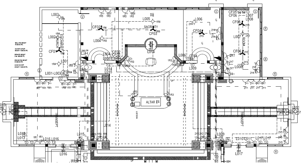
Figure 2.8: Part of Electrical Layout Design
After first designing I had a meeting with Dr.Tilak Siyambalapitiya and discussed for correction which occurs due to practical problems. As a lot of modifications had been done to the original design (according to the requirements of the Church) and civil constructions had been done to a certain extent. Especially the lay out design was little bit easy because of the symmetry of the building plan.
2.1.3.1 Single Line Diagrams
Single Line Diagrams are the schematic drawings of all the electrical circuits which include cable sizes, MCB/MCCB ratings, RCD ratings etc., but they don’t give us an idea about the actual layout of the circuits. The SLD of one DB of church electrical design is shown below.
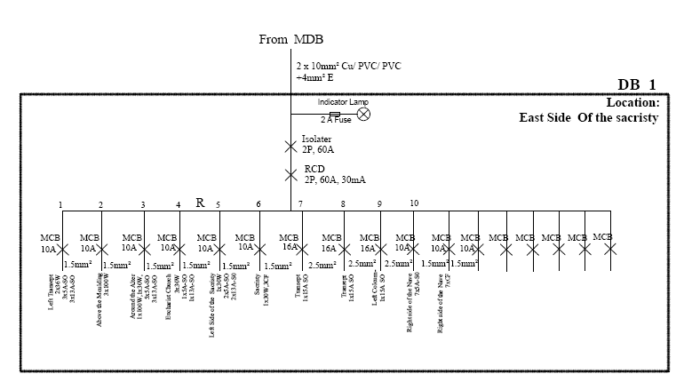
Figure 2.9: Example for a Single Line Diagram
2.1.3.2 Load Calculation
I did the load calculations for building block M of the Maris Stella Branch School. This load calculation is also very important in cable sizing & MCB/MCCB selection.
- Utilization factor (ku)
This implies which fraction of the nominal power rating of each individual load is consumed by them in normal operating conditions.
E.g.: For electric motors- 0.75
For incandescent lamps- 1
For socket outlets- Depending on the appliances
- Simultaneous factor (ks)
This is a matter of common experience that the simultaneous operation of all installed loads of a given installation never occurs in practice. This factor is applied to each group of loads & always less than or equal to 1. This is also known as Coincidence factor which is the reciprocal of Diversity factor.
A part of load calculation was done for DB17 is shown in Figure 2.12 below.
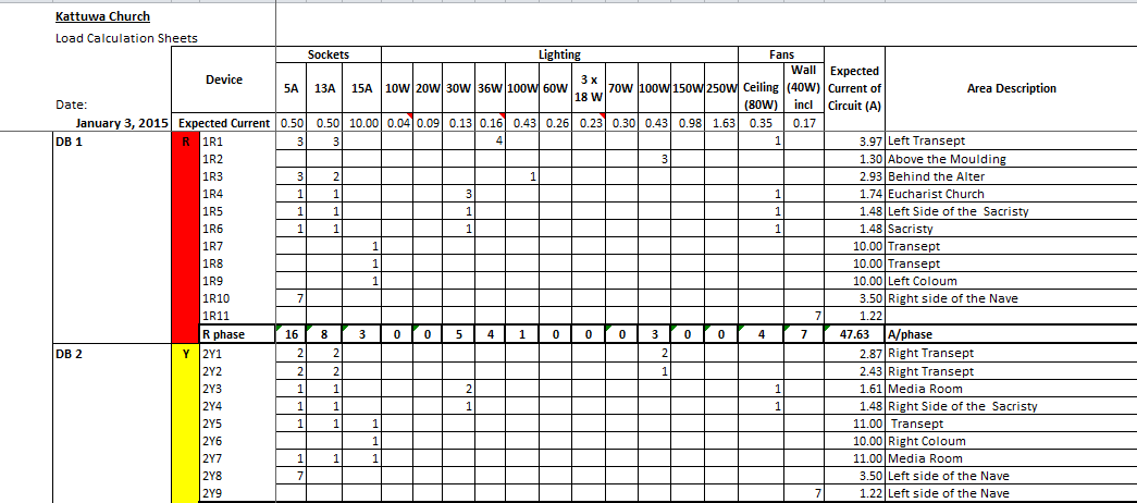
Figure 2.10: Sample for a Load Calculation
2.1.3.3 Cable Sizing and Cable Protection (MCB/ MCCB selection)
After doing load calculation for each cable, cable selection was done. Some DBs had much distance from main DB and some lighting circuits were much long.So cable selection was done by considering the voltage drop too. There, derating the current carrying capacities of the cables was also done considering temperature correction factor, grouping factor and installation factor. Then MCB/MCCB selection was done with the purpose of protecting each cable.
2.1.3.3.1 The difference between a MCB & a MCCB
MCCBs can carry larger currents and also their operating current is settable. MCBs with the protection purpose have to be used at the beginning of a cable but, by applying them at the end of cable, isolating a major load can be done.
MCBs are available for both single phase & three phase circuits. Also they are categorized as 1Pole, 2Pole (for single phase) or 3Pole, 4Pole (for three phase) implying whether they have the capability of disconnecting the neutral too.
Rule of thumb for MCB selection for widely used cable size (cross sectional area)
1 mm2 – 6A MCB
2.5 mm2 – 10A MCB
4 mm2 – 16A MCB
6 mm2 – 20A MCB
10 mm2 – 30A MCB
16 mm2 – 60A MCB
Ceylon Electricity Board (CEB)
The training contract and the 12 weeks schedule for the CEB training was given to me by the CEB training center at Piliyandala. The total training was from 2nd of February 2015 to 23rd of March 2015 at CEB training locations. According to the given schedule, I had the training for eight weeks in CEB with a group of seven other members. During this period I got good knowledge about electricity generation and transmission in Sri Lanka.
My Training Schedule for CEB can be see in ANNEX.
Hydropower Generation –Randenigala and Rantambe Hydro Power Stations
2.2.1.1Overview of Mahaweli Complex
Mahaweli Hydro power complex consists of seven major power stations which has an installed capacity of 810 MW. This complex contributes around 15% electrical energy to the country annually. Mahaweli project was implemented as a multipurpose project under the accelerated Mahaweli scheme which was started in early eighties with a view to complete within six years.
The main objective of the Mahaweli system is to provide water to irrigation and other usages. Power generation is the secondary purpose. Ceylon Electricity Board and Water Management Secretariat of Mahaweli Authority of Sri Lanka jointly decides the water utilization of these reservoirs, in a manner which both parties benefit, ultimately giving the maximum benefit to the country.
Mahaweli Complex hydropower system consists of, Kothmale, Victoria, Polgolla, Randenigala and Rantambe reservoirs. And the The major power stations coming under Mahaweli complex are, Kotmale, Victoria, Randenigala, Rantambe, Ukuwela, Bowatenna, Upper Kotmale and Nilambe.
2.2.1.2 Introduction to Rantambe Power Station
Rantambe power station is designed as an energy distribution station with a five feeder 220/132 kV outdoor switchyard including two 132/33/12.5 kV main transformers, three single –phase auto transformers and 33kV indoor switchgear with 8 feeders.General Details of Rantambe Power Plant as follows.
Average annual rainfall2, 550mm
Average annual inflow 3,510 million m3
Reservoir
Retention water level 152.0m MSL
Design flood level 153.0m MSL
Minimum water level 140.0 MSL
Active storage 17.6 million m3
Total storage 21.0 million m3
Surface area 1.8 km2
Dam
Type Concrete gravity
Height above foundation 41.5m
Crest Level 155.5m MSL
Crest length 420.0m
Crest width 10.0m
Concrete Volume 200,000 m3
Spillway
Gates 4tainer
Width/height 16.0×16.4m
Design discharge 6,300 m3/s
Maximum capacity 10,235 m3/s
Bottom Outlet
Revision gates 2slide
Width/Height 2.55×3.80m
Service gates 2tainer
Width/Height 2.55×3.60m
Power Intake
Revision gates 2 slide –roller
Service gates 2Slide
Width/Height 4.30×4.81m
Design discharge 2×90 m3/s = 180 m3/s
Sill elevation 126.0m MSL
Penstock
Diameter 4.30m
Length approx.20m
Slope 50%
Power House
Type above ground
Average gross head 335m
Average net head 32.7m
Turbines 2 Francis
Rated Speed 166.7 r.p.m
Turbne discharge 2×90 m3/s = 180 m3/s
Installed Capacity 2×24.5 MW = 49 MW
Dimensions(LxWxH) 35.4×14.3×43.0m
Switchyard
Generating Voltage 12.5kV
Rated Voltage 220kV/132kV
Average Annual energy production 251GWh
2.2.1.3 Turbines
Turbine selection mainly depend on the head of the reservoir.
- High Head, Low Flow– Pelton Turbine
- Medium Head, Medium Flow– Francis Turbine
- Low Head, High Flow– Kaplan Turbine
Rantambe Power station has two francis turbines. Also there is no main inlet valve in the rantambe power house.
2.2.1.4 Generators
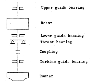 The three phase synchronous hydro-generator with salient pole rotor directly driven from Francis turbine. The generator has two combinations of thrust and guide bearing.one of them is below the rotor and other is above it. The generator is semi umbrella type generator.
Figure 2.11. Generator and rotor bearing arrangement
The generator is provided with closed system ventilation, consisting of six air/water coolers. The air circulates partly through the generator and partly through the foundation channels.
The stator is provided with six terminals for the electric connection of the stator winding .Three of them are leads to the phase winding ends. They are used to build the star point (neutral terminals).The other three are used to build the main generator terminals.
The generator windings are insulated with class F insulation corresponding to the present standards.
2.2.1.5 Main Transformers
Each generator is connected to a Main three winding transformer. The transformer kVA ratings are as follows
| ONAF | ONAN | |
| System 1 / 132kV side | 34500 | 22500 |
| System 2/33 kV side | 10000 | 6500 |
| System3/12.5 kV side | 34500 | 22500 |
Figure 2.12. Transformer raring corresponding to the cooling methods
Vector group is YNd11/d11. It is helpful to reduce the space.
Also Rantambe has a single phase Auto Transformers which are 132kV step-up to 220kV and transformer capacity is 35MVA.
2.2.1.6 Active power control
To control active power we must control the mechanical power supplied to the generator , by the turbine.This is done via a heavy Electro-Mechanical device called “Turbine Governor”. The Governor offers the remote control facility at the operators desk.
Governor Operation
A hydraulic turbine is required to run at the same constant speed as that of the electric generator to which it is directly coupled . This synchrous speed must be maintained for all conditioned of load on the generator.But since the demand for the power fluctuates with time, the hydro unit must adjust to itself to such variations in load in such a way that the turbine speed remains constant/unaffected.whenever the load on the turbine decrease ,if the discharge entering the turbine is not adjusted accordingly,its speed will increases.On the other hand ,increase in load will tend to reduce the turbine speed unlesss the turbine discharge is increased in accordance with the new load. Such regulation of discharge with a view to maintain a synchrous speed of the turbine runner is called governing of turbine. and is done automatically by means of a governer.
The speed governor has the following major functions:
- To take the generator to the rated speed as fast as possible without much delay
- To allow the synchronization of the generator.
- To act so that the turbine-generator unit supplies the required active load when needed
- To change the load on the generator.
- To carry out frequency correction (if it is necessary).
- To control the turbine-generator during disturbance conditions.
We have to maintain frequency of generated power as 50 Hz. To keep it constant it is important to keep the speed constant. That is obtained by the governor. Governor has a speed feedback. According to that, governor controls the water amount comes into the turbine by controlling the wicket gates.
For example, if load is increased from 40 MW to 50 MW. Then speed of turbine will decrease. So, governor senses that variation and it will admit more water by opening wicket gates further.
The governor has two modes of operation
- Load limiter mode
- Frequency mode
Reactive power control
To alter reactive power output of a generator we should alter its excitation. This is done via a unit called AVR (Automatic Voltage Regulator).
- To raise Reactive Power we should raise excitation
- To lower Reactive Power we should lower excitation
In the running operation of the AVR, if a reactive power load goes up the terminal voltage Vt will fall, which in turn is detected by AVR and takes corrective actions to raise the excitation and thereby regaining the set Vt.
Excitation Systems
An electric generator or electric motor consists of a rotor spinning in a magnetic field. The magnetic field may be produced by permanent magnets or by field coils. In the case of a machine with field coils, a current must flow in the coils to generate the field; otherwise no power is transferred to or from the rotor. The process of generating a magnetic field by means of an electric current is called excitation.
In Rantambe power station, the generator field winding is supplied by from a static excitation system. The excitation power is taken from the generator’s terminals via the excitation transformer, the controlled rectifiers, carbon brushes and slip rings to the rotor winding .The automatic voltage regulator controls the thyristors over the grid control and the pulse amplifier in such a way, that the generator voltage is constant between no load and rated load. The rectifiers are connected to a fully controlled three-phase–bridge, which allows reversing of the polarity in the exciter field. This effects a high controlling of speed during build–up as well during reduction of the field current. For initial excitation is the generator fed by a three-phase auxiliary network over transformer and rectifiers.
Rotor DC Winding
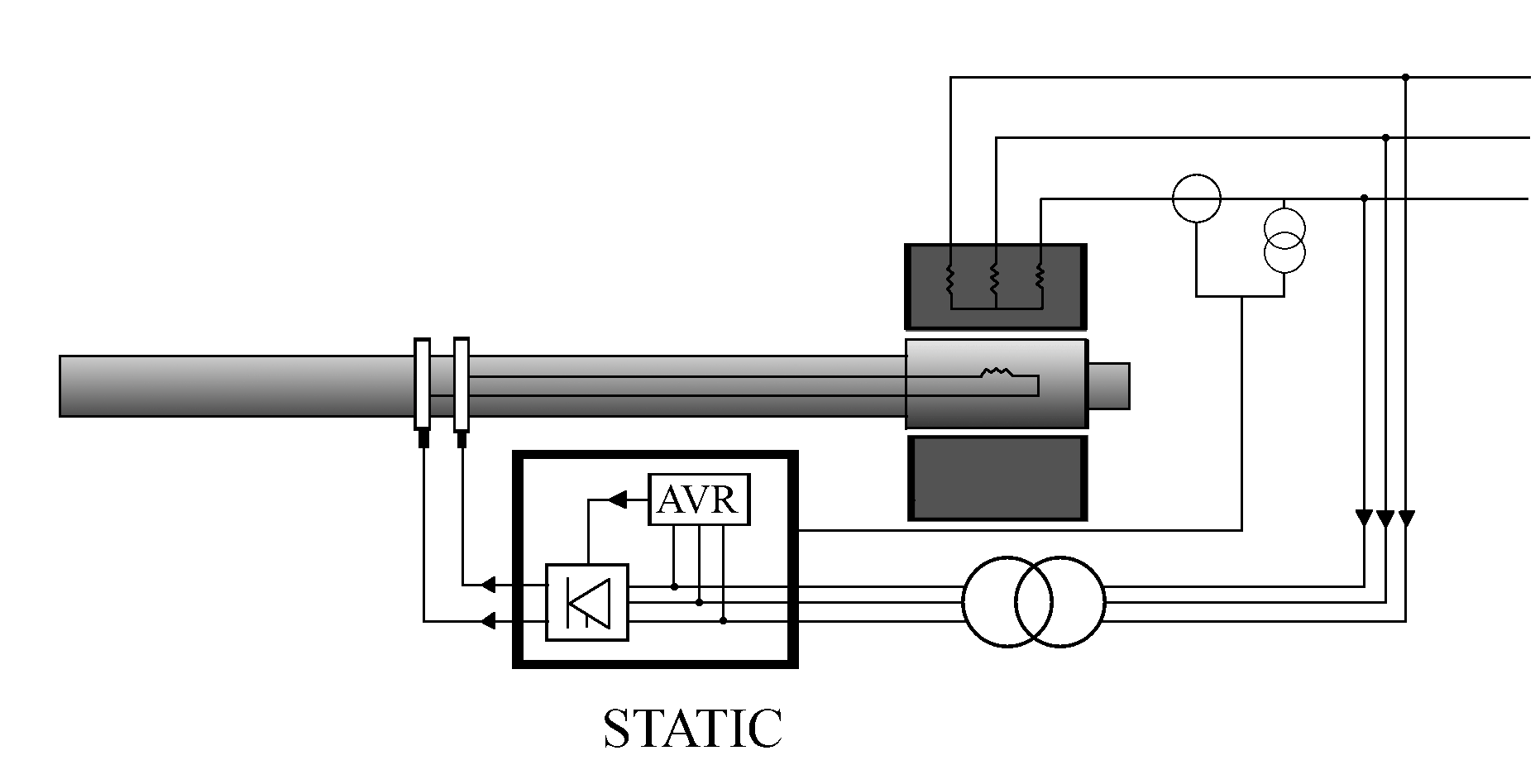
Stator and rotor
Step down transformer
Brushes
Figure 2.13 Excitation System of Rantambe power plant
Switchyard and Transmission Lines
The 132/220 kV Rantambe switchyard contains the following:
- Double bus bar system
- Two transformer feeders for main transformers
- Two transformers 132/33/12.5 kV 34.5MVA with off load tapchangers
- One transformer feeder for coupling transformer
- Three single –phase auto transformer 3x35MVA with on load tap changer (motor driven)and AVR
- One single phase auto transformer (35MVA) as spare
- One overhead line feeder 132 kV (Line Badulla)
- One overhead line feeder 220 kV (line Randenigala)
All feeders are equipped with isolaters, circuit breakers, CTs, VTs, surge arrestors, line traps, control, alarm and protection equipment, and local control cubicles.
Also 33kV indoor switchgear room located in the control building contains following:
- Single bus bar system
- One feeder station aux. Rantambe
- Two feeder incoming from main transformers
- Three feeder outgoing lines 33 kV network
- One feeder station aux. Randenigala via overhead line
- One feeder 33kV system earthing
One Peterson coil and one earthing transformer, for system earthing , are installed in the switch yard. One station auxiliary transformer 33/0.4kVA for the station auxiliary supply is installed.
Randenigala Power station
Randenigala power station has many similarities with Rantambe power station discussed before. Diffents between the Rantambe and Randenigala power plants are
- Randenigala power house has main inlet valve
- Has Black starter for blackout restorations
- Head is 72m and has same water discharge rating
When considering the protection schemes of both power plants,
- Generator protection
- Line protection
- Busbar protection
- Transformer protection
- There is fire protection as well
Thermal Power Generation _ Kelanitissa Thermal Power Complex
Kelanitissa thermal power coplex is comprised of two plants, Kelanitissa Power Station (KPS) and Kelanitissa Combined Cycle Plant (KCCP). They are functioning as two different units separated from each other.
Kelanitissa Power Station (KPS)
I was assigned to Kelanitissa Thermal Power Plant during the first week of the training period. It contains of seven diesel gas turbines in the plant where the plant has a total capacity of about 195 MW. The Table 2.1 shows details about each gas turbine (GT). This power station was commissioned 1964. There are 6 gas turbines (GT-1,2,3,4,5,6) each having capacity of 20 MW and a larger gas turbine (GT 7) having capacity of 115 MW in KPS. From those gas turbines one 20MW turbine (GT 6) is not in a operational condition.
The rated speed of the turbine is 5100 rpm. Generator rated speed is 3000rpm.
2.2.2.2 Basic Operations
The importance of Kelanitissa Thermal Power Station (KPS) despite of the high running cost,
- Peak handling of the load profile
- Fast start and the first to turn on during a blackout
- Dynamic reactive power (var) supply for voltage stabilization
- Colombo emergency supply
|
|
|
|
|
| ||||||
| GT1 |
|
|
|
|
| ||||||
| GT2 | |||||||||||
| GT3 | |||||||||||
| GT4 | |||||||||||
| GT5 | |||||||||||
| GT6 | Not Operational | ||||||||||
| GT7 | 115MW | Using 6kW motor |
|
| |||||||
Figure 2.14 General details of KPS generators
Figure 2.15: Basic Operation Units of KPS
The generators are cylindrical rotor type. Through the air filters normal air is taken in and directed to the compressor. Then the air is compressed and directed into the combustion chamber. Inside it the atomized air and fuel gas are burnt. Then create high pressure, high temperature gas. This gas flow rotates the turbine in high speed. Baring motor is used to rotate the turbine to avoid self-sagging when plant is stopped. The turbine rotation is used to drive the compressor also.
Synchronous Condenser Mode
Sometimes the generators run in this mode. At this requirement generator decouple from turbine and generator work as a synchronous motor. A synchronous motor takes a leading current when over excited and therefore behave as a capacitor. An over excited synchronous motor running on no load is known as synchronous condenser. When such a machine is connected in parallel with the supply ,it takes a leading current which partly neutralizes the lagging reactive component of the load .Thus the power factor is improved.
2.2.2.4 115MW Large Gas turbine (GT7)
This 115MW generator is also having same operation principle; differences are it consists of 1MW high torque motor to start the GT and due no disengaging gear box to disengage generator and turbine. Baring and other all process are required in here also. Starting process of this GT is as same as the GT start in combined cycle power plant GT.
GIS and Switchyard
The switchyard in KPS is having 220kV, 132kV and 33kV. The small GTs except GT1, are connected to the 33kV busbar through 10.5/33kV transformers.. The GT1 and the GT7 are connected to the 132 busbar through 10.5/132kV transformers. This busbar is a UI type busbar system. The 33kV busbar is connected to the 132kV busbar through 33/132 kV inter bus transformer.
The power generated in KPS is transferred to the Kolonnawa through 132kV double circuit transmission line and to Biyagama through 220kV double circuit transmission line. The Biyagama lines are connected to the switchyard through 220/132kV step-down transformers and a gas insulated substation.
There are 220kV and 132kV two GIS (gas insulated switchgear) in the power station. In GIS all the switching functions are possible as in normal outdoor switch yard. Insulation gas medium is SF6. Advantage of having GIS is less space is required. So, GIS is more suitable for urban areas where less space is available. Breakers, isolators, bus bars and all components are inside the pressurized SF6 medium.
Figure 2.16 Single line diagram for 132 kV and 220 kV GIS
Thermal Power Generation-Sapugaskanda Power Station
Sapugaskanda power station consists of two stations called station A and station B. The installed capacity of station A is 80MW (4 x 20MW) and station B is also 80MW (8 x 10MW).
Station A
Station A has four 20 MW machines. Engine manufacturer is Pielctick and engine type is PC 4-2 18V. Rated speed of one machine is 428rpm. For each 9 cylinder set one turbo charger is attached to get inlet air and to exhaust the air. The generators are rated at 26.5 MVA and the power factor of 0.85. Output voltage is 11 kV. The rotor is a salient type one which got 14 poles. Rated current of the generator is 1300 A. The generators are separately excited using an excitation voltage of 63V and current of 57.5 A. There were two step-up transformers (SUT) at station A and capacity of each transformer is 50MVA. Two station service transformers (SST) were there and capacity of each SST is 3150 kVA.
- Fuel consumption of station A
For diesel fuel – 0.26 l/kWh
For heavy fuel – 0.24 l/kWh
- Plant efficiency
For diesel fuel – 26%
For heavy fuel – 40%
2.2.3.1.1 Systems Attached to the Engine
- Fuel oil system
- Lubrication oil system
- Jacket water system
- Injector water system
- Cooling water system
- General water system
- Intake air and exhaust system
- Hot water system
- Sludge system
- Compressed air system
7 bar air(control)
30 bar air (starting)
- Electrical system
2.2.3.1.2 Some Engine Protections Used
- Electronic over speed – Tripping level 485 rpm
- Backup over speed – Tripping level 514 rpm
- Lubrication oil temperature – Tripping value 650C
-Alarm level 600C
- Lubrication oil pressure low – Tripping level 4 bar
-Alarm level 4.7 bar
- Main bearing temperature – Tripping level 940C
- Jacket water temperature high – Tripping level 950C
- Oil mist detectors were attached to the engines.
Station B
Engine manufacturer is MAN B & W and engine type is 8L 58/64. Section B consists with two parts. B1 and B2 each section has four 10 MW generators which now operates at maximum 9 MW due to machine ware and depreciation. This works under 4-stroke engine principal. Engine has eight I type cylinders. The generator is rated at 12.9 MVA with a power factor of 0.8. Output voltage is 11 kV and the rated current 677 A. The sync speed of the generator is 428.6 rpm. The rated excitation voltage is 77 V and current is 415 A. There were three step-up transformers (SUT) at station B and capacity of each transformer is 50MVA. Three station service transformers (SST) were there and capacity of each SST is 2000 kVA.
- Fuel consumption of station B
For diesel fuel – 0.23 l/kWh
For heavy fuel – 0.21 l/kWh
- Plant efficiency
For diesel fuel – 38%
For heavy fuel – 44%
Electrical Aspects of the Power Station
2.2.3.3.1 Generator protections
- Generator differential protection
- Restricted earth fault protection
- Alternator negative phase sequence
- Voltage restrained overcurrent
- Reverse power
- Over voltage
- Under voltage
- Rotor earth fault
- Bearing metal temperature
- LV fuse melting
- MV fuse melting
- Over frequency
- Under frequency
- Under excitation/loss of field
- Diode failure
2.2.3.3.2 Excitation system
Diode bridge
AVR
Pilot Exciter
Main Exciter
Generator
S
R
R
S
11kV
Figure 2.17: Block diagram of excitation system
Station A – Pilot exciter is a Permanent Magnet Generator (PMG).
Station B – Pilot exciter is a 5 phase winding mounted on generator stator winding
In Station A, in AVR thyristors are used. A set of three thyristors is used for auto operation and another set is used for manual operation. At the starting the pilot exciter is used. In AVR half wave rectification is carried out.
In Station B, in AVR a set of ten thyristors is used for auto operation and another set is used for manual operation. By using 5 phase winding we can get a smooth DC voltage. At the starting residual flux of 5 phase winding is used for excitation.
Kurunegala (Mallawapitiya) Grid Substation
2.2.4.1Introduction
This substation belongs to the Kandy region of Transmission Operation & Maintenance section. Kurunegala GS has 132kV system, 33kV system and a capacitor bank. This is connected to Kiribathkumbura GS through a 132kV double circuit transmission lines. The incoming power through the 132kV line are taken to 132kV busbar and transformed to 33kV through two 3 phase transformers. These transformers connect to 33kV bus bar and out as nine 33kV lines to Ibbagamuwa, Mawathagama, Kurunegala, Narammala, Maho, Padeniya, Galagedara and Dodangaslanda.Here 33kv side has a GIS(Gas Insulated Switchgear).
2.2.4.2 Equipment in substations
- Switching equipment
- Transformers
- Power transformers
- Auxiliary transformers/ Earthing transformers
- Instrument transformers
- Control and protection equipment
- Earthing system
- DC power supply system
- AC power supply system
- Communication system
2.2.4.2.1 Switching equipment
Switching equipment used are earthing switches, isolators, circuit breakers and bus bar arrangements.
- Isolators
Isolator is a mechanical switch which is operated in no load condition. This is an open type switch and, it could be seen whether the isolator is open or closed physically. If an isolator is operated in on-load condition, the arks could be generated. This device is used for isolating the busbars and the breaker from the power system. This isolation is visible and ensures the safety of workers. Isolators cannot be operated with the breakers at on position.
So, as a practice the isolators are operated after the breaker. There are horizontal break type, vertical break type, center break type and pantograph isolators.
- Circuit Breaker
Circuit breakers are used to connect or disconnect power lines in either no-load or on-load conditions without developing arcs. These breakers have the facility of opening & closing under normal conditions and also in faulty situations. And can be operated manually or remotely.
Circuit breaker types are as follows,
- Air circuit breaker
- Air blast circuit breaker
- Vacuum circuit breaker
- Oil circuit breaker
- SF6 circuit breaker
Circuit breaker operating mechanisms,
- Spring charging mechanism
In spring charge breakers in normal conditions there is a spring set charged by motors. When the signal is given when a fault occurs the spring stored-energy actuator is tripped. Then the connection is broken inside the pole.
- Hydrolic system
- Pneumatic system
In Pneumatic operated breakers there is a solenoid. When the signal is sent the coil will be energized and act as a magnet. A metal part is attracted to it such that this movement will release the pressurized air gathered inside below the breaker part. Eventually the moving contacts are pulled down.
- Bus bar
In power systems, the bus bars are acted as the modes or vertices of the network. There are various kinds of bus bars used in Grid substations. Single bus, double bus could be taken as the examples. In double bus bar systems, bus couplers are used to connect the busses. But in single bus systems, most of the time, bus sections are used.
2.2.4.2.2 Transformers
There are power transformers, auxiliary transformers, earthing transformers and instrument transformers in the substation.
- Power Transformers
Normally transformers are critical and expensive components in grid substation. Therefore protection is essentially required to limits damages to transformers while the operating condition because high cost and long outages if transformers failed. Failures of transformers are categorize as follows,
- Winding failures
- Core faults (core insulation failures)
- Terminal failures
- On load tap changer failures (mechanical, electrical, short circuit, over heat)
- Abnormal operation condition (over fluxing, over load, over voltage)
- Other external faults
- Transformer Protection
- Hot spot temperature-
- Dehydrating Filter Breather –
- Gas and Oil Actuated Relay ( Buchholz)-
- Pressure relief valve-
- Instrument Transformer
- Current transformers
The current transformers are normally used as a measuring instrument in the areas like protection and measurement. In here the power line is used as the primary winding and a secondary winding is created around the power line. The current generated in the secondary winding is proportional to the current carrying through the power line. There might be multiple cores used in different purposes, in a single CT. The secondary windings of a CT should always in a closed circuit during the operation. Otherwise, the CT could be destroyed with huge blasts.
- Voltage/Potential Transformer
The voltage transformers, commonly known as VTs are generally used in protection and instrumentation purposes, as a measuring instrument for voltage. One end of the primary winding of VT is connected to the power line and the other end is connected to the ground. The secondary winding is placed such that, the voltage is lower than the primary winding’s. One terminal of the secondary winding too connected to the ground.
2.2.4.2.3 Surge arrestors
Surge arrestors, which are commonly known as lightning arrestors are used in protection from the higher voltage surges. As a practice this equipment is applied to protect the high reliable and high cost equipment. As a practice, SAs are used in connection point of every power line connected to the GSS and the both primary and secondary sides of the power transformers.
2.2.5 Transmission and Generation Planning Branch
As a main power producer in Sri Lanka, CEB’s main duty to develop and maintain an efficient, coordinated and economical system of electricity supply for the whole Sri Lanka. Because of this reason CEB is required to generate or acquire sufficient amount of electricity to satisfy the demand. Then CEB methodically plans its development activities in order to provide reliable, quality electricity supply to the entire nation at affordable prices.
Transmission and Generation Planning Branch of CEB, published main two reports
1. Long term generation expansion plan (for 20 years)
2. Long term transmission plan (for 10 years)
2.2.5.1 Long term generation plan
This report mainly includes information on the existing generation system, generation plan methodology, system demand forecast, investments and implementation plans for the proposed projects and recommends the adoption of the least cost plan sequence derive for the base case and also emphasize the need to implement the plan to avoid energy shortfalls.
2.2.5.1.1 Electricity demand forecast methodology
CEB mainly use the econometric modeling for the future demand forecast. In these models, the sales figures of the past were analyzed against several independent variables using regression techniques.
| Domestic sector | Industrial Sector | Commercial Sector |
| 1.GDP 2.Previous year demand 3.Past demand | 1.GDP 2.Previos year GDP and demand 3.Deamand |
Figure 2.18 Variables used for econometric modeling
Time is used as variable for religious purpose and street lighting and used time trend method.
- By using SPSS (statistical package for social science) software we can find the correlation of these variables with past demand with 25 years back. Hence we can forecast the future demand by using these techniques.
- Loss forecast – By taking details from distribution division and transmission we can find the existing loss and future losses considering expansion of line and etc.
- Generation Forecast
Total Generation = Demand + Loss
- Peak calculation for future
Peak =
Here load factor can find by using past year load factors, and assume load factor will vary linearly.
WASP Software ( Wein Automatic system planning )
WASP is used to find the commissioning year for best matching power plant by considering cost optimization. Here we should input several details for WASP software.
- Peak and load factors.
- Existing system details.
Here we enter the existing system hydro, thermal and NCRE details. Also enter the addition and retirements years of those plants.
- Candidate power plant details.
- Other system parameters
Ex: Spinning reserves, Reserve margins etc.
System Control Centre, Dematagoda
I obtained one week of experience at the system control centre of CEB. The Shift Charge Engineers explained to our group of trainees the role of the system control centre, its operations and operation policies followed. I acquired the knowledge on the merit order of economic dispatch and I studied about the demand – supply matching as well as about the hydro machines (New Laxapana, Kotmale, Victoria and Samanalawewa) that are used for frequency control. The droop characteristics of those frequency regulating machines and a base load running machine was compared and explained by the SCE. Performance of Sri Lankan electricity network is controlled and monitored by System Control Centre (SCC) at Dematagoda.
Also the SCE explained about the energy planning, forecasting, water value and the methodology of hydro power plant dispatching. The fact that the spinning reserve of the system should not be less than 5% of the gross generation at that instance was also elaborated. Furthermore, he stated that the maximum single generator unit should be less than 20% of the gross generation at that particular time. The SCADA system was observed and the SCE showed the past load profiles using the computer system. The system operation priority is as follows,
- The safety of the people
- Protection of equipment
- Availability of supply according to the demand
- Quality of the supplied power
- Operating the system in the most economical manner
I got the knowledge on the charges incurred at operating and dispatching thermal power plants such as the start/stop charge, capacity charge and the heat rate charge. These charges are different from each power plant according to the agreement.
System Stability Limits
- System frequency should be 50 Hz ±1%
- Main system voltages should be as follows.
| System Voltages | Required Voltage Limitations |
| 220 kV | Between +10% to -10% error range |
| 132kV | Between +10% to -10% error range |
| 33kV | Between +2% to -2% error range |
Table 2.19: System stability limits
System Operation
System operation means the controlling process of whole power system by communicating with all plants and Grid Substations. This is the task should done by the operation Engineer of the system control center. Plant connection and dispatching is not a random task. It is done according to a planning process.
There should be a spinning reserve. This margin should not less than 5% of gross generation.
- Maximum Generator Unit –
The maximum load in any generator unit should be less than 20 % of the total demand. In thermal generation maximum generator unit can load 22.5% of total demand. It is to avoid any blackout situation if any plant trips.
Operation Planning
According to the load curve, to satisfy the demand generation should be planned by considering losses also. For maintain of plant, grid substation or Transmission line outage planning should decide in the systematical way to minimize to disturbances to the system.
Choosing of thermal power plants is depends on start/stop cost and unit cost of the thermal plants. But decisions relevant hydro power plants are more complex. The main hydro power complexes are Mahaweli and Laxapana hydro power complexes. So the raining pattern of the year must be considered in order to select the more suitable complex. The Laxapana complex is totally owned to CEB and can be use the water in the complex at any time. But Mahawelli complex is not only for power generation. Water usage priority as follows,
- Water services and drainage
- Environment
- Irrigation
- Power generation
So the operation of the power plants of Mahaweli complex should follow the plans got by water management meeting. The water levels of the reservoirs and ponds and cascading arrangement of the ponds are also considered by the system control engineer in order to select the running power plant. There is a parameter called water value depends on water level which is affecting to the power plant selection.
Normally system control Engineers works with historical data and with their past experience. According to the predicted demand curve they inform power station to connect, remove, increase and decrease their power. For that they make daily dispatch schedule and send them to the relevant power stations individually.
2.2.6.2.1 Pond Balancing of Laxapana Complex
Briefly, maintain the pond levels to take required generation at required time.Mainly two factors affect for the pond balancing.
- Availability of the machine
- Weather
2.2.6.2.2 Salinity Effect
When maintaining the ponds of Laxapana complex it is affect to the water level of Kelani River. Ambatale is the water treatment plant which supply water to Colombo area. When laxapana complex storing the water at reservoirs and ponds kelani river’s water level will goes down and at tidal time periods sea water comes in to the country through the Kelani river. This mainly affect for the water treatment plant at ambatale and when doing pond balancing at these time periods it should consider about the salinity effect.
Under Frequency Load Shedding
Under Frequency Load shading concept is important if suddenly large load connected to system or if a plant trip off due to fault. Then that system becomes unstable at such moment frequency controlling machine also may not possible to bear the impact. Frequency is decreasing rapidly this may cause cascade tripping of generators and may cause total black out, system can regain the stability by reducing loads from the system. Feeders should cut off automatically to reduce the load. According to following table feeders are cutoff by breakers.
| Frequency (Hz) | Schedule of Load cut out |
| 48.75 | 05% of the load cut out from the system |
| 48.50 | 10% of the load cut out from the system |
| 48.25 | 25% of the load cut out from the system |
| 48.00 | 35% of the load cut out from the system |
| 47.50 | 45% of the load cut out from the system |
Table 2.20: Under frequency load shading schedule
Frequency Control
Usually frequency control of whole electricity network is done by a selected hydropower plant. Mainly Kotmale, Victoria and Samanalawewa power plants are used for this. The reason for using these machines for frequency controlling is that these machines can smoothly change the power output. Then it can control its power according to demand variation and maintain the frequency within the range.
Lanka Electricity Company (Pvt) Ltd. (LECO)
Four weeks of my Industrial Training from 19/01/2015 to 30/01/2015 was scheduled to be at LECO Head Office and from 30/03/2015 to 12/04/2015 was scheduled to be at Kelaniya branch office and Dalugama Customer service center. Also we could get a chance to visit the LECO Meter testing lab and transformer work shop at Ja-Ela. I got the exposure in the field of Electricity Distribution of the LECO region during this period.
System Operation Division, Head Office
2.3.1.1 Network Operating Centre
LECO power distribution system is controlled by Network Operating Centre (NOC). This section deals with every operational activities are done by branch offices and customer services centres. On shift basis there are about two personals on duty every time. There is a display board known as mimic board to display the current situation of the system. The primary responsibility of NOC is to maintain the reliability of power supply and safety of power distribution system.
Interruption Scheduling
Interruptions are planned power cuts. Interruption requests are made by LECO CSCs or by CEB from the LECO Distribution Control Centre. Considering CEB requests LECO NOC decides their interruptions. For example when CEB shutdowns a primary substation, LECO interruptions relevant to that substation is scheduled that day. Likewise NOC decides the interruption dates and publish newspaper notices and send letters especially to the bulk customers who will be affected by the interruption. Also they send letters to the relevant CSCs. This letter to CSC includes the switching instruction and switching diagram.
- Work Permit
This is issued by Custom Service Superintendent (CSS) or the Branch Engineer to the technicians or the workers who are going to carry out the work within the isolated area. To issue a work permit minimum two earths are required. This is kind of a document ensuring the workers it is now safe to carry out the work. CSS informs to NOC when he gives the work permit and cancels the work permit when the job is done.
Engineering Division, Head Office
One of design engineer explained the basics about the LECO distribution system and the GIS mapping. He further explained about the GPS satellite system and the manner of locating the position. We had a discussion with the GIS mapping draughtsman and learnt about the mapping assets of onsite equipment which LECO follows using GIS maps. I learnt about data collecting and the method of drawing GIS maps as well.
2.3.2.1 Geographical Information System Mapping Procedure
1. Data which take from each transformer poles, transformers, poles and etc. on distribution feeders and lines are input to the GPS data logger.
2. These GPS data logger data input to the terrasync software and create GPS data files.
3. GPS data files input to the GPS path finder and we can get properties of equipment in distribution line from this software. GPS path finder create files with reference geographical software (online) which name is differential corrections.
4. After differential corrections these files imported to AutoCAD software and point details were converted to visual drawings.
I learnt about the procurement procedure of assets from local and international vendors at the LECO. Also I learnt about the stock management system that LECO uses to monitor all their assets in the stores, branch offices and in the customer services centers using the Pronto software. I further learned about the distribution system of LECO and its configuration.
2.3.3 Construction manual
Construction manual consists of four volumes. These volumes describe about concepts and design criteria, general arrangements and drawings, equipment selection charts and equipment drawings regarding to construction and maintenance of distribution lines. These manuals are there to guide the personals to have a standard distribution system and good practice of Engineering.
Purchasing
LECO follows purchasing criteria for every purchase requirement. First when there is a need of materials for the stores, a purchase requisition is made to the engineering division of the Head Office. Then the registered bidders (suppliers) are invited to state their offers to the items which are to be bought. With this inviting letter LECO attach the specifications and request for price schedules, test certificates, samples etc. At a given closing date at the division premise, the bids are opened and sort out who the best supplier to be who has fulfilled the most technical requirements the specific job ask for.
Training Centre, Ja-Ela
I observed the configuration of an energy meter and how to test analog meters. I got to know how to use the Megger to test a transformer for its insulation. Also I observed the oil treatment plant
Meter Testing
Meters are tested according to two IEC standards. They are IEC 62053 and IEC 62052. According to IEC 62053, following test conditions should be maintained.
- Temperature 25 0C ± 2 0C
- Frequency 50 Hz ± 0.5 Hz
- Power factor variation-Rated value ±0.01
- Voltage fluctuations ± 1%
- Angle to vertical absolute at hanging meters 0.50
- Routine Tests
- Starting test
- Apply rated voltage and 5% of rated voltage to the meter.
- The rotor shall complete one revolution.
- Creeping test
- Apply 80% to 110% of rated voltage to the meter with no current.
- The rotor shall not complete a revolution.
- Anti-reverse test
- Apply rated voltage and a reverse current of magnitude in the range of Ib to Imax.
- The rotor shall not continuously move on reverse direction.
- Percentage Error Limits Test
- 1.0 P.F and Imax -2 ≤ % Error ≤ +2
- 0.5 P.F lag and Imax -2 ≤ % Error ≤ +2
- 1.0 P.F and 2Ib -2 ≤ % Error ≤ +2
- 0.5 P.F lag and 2Ib -2 ≤ % Error ≤ +2
- 1.0 P.F and 0.05Ib -2.5 ≤ % Error ≤ +2.5
Megger Test
Transformers are checked for its continuity and insulation using a meter called Megger. This test is called Megger Test. We check the HV-LV, HV-earth, LV-earth sides of the transformer. For good insulation the Megger value should be 100 MΩ or above.
Transformer repair
Transformers go out of function due to lightning strikes, oil leakages, short circuited inside etc. When water is mixed with oil refilling of oil is needed. Oil is checked by the oil tester before refilling. In oil tester normally get 6 readings. Breakdown voltage should be greater than 35kV. Oil is taken from bottom valve of the transformer. If water is there in transformer oil, transformer will fail if the oil stirs
Branch Office – Kelaniya
First day we met the Branch Engineer and gave us a brief introduction about LECO and its history, the administration side of the branch, distribution system of LECO, benefits found in LECO. Also I could get the idea about customer billing, how a domestic bill is calculated, the process of giving new connections and LV design etc. Construction Engineer gave brief description about transformer selection, phase balancing, and software used to design distribution system.
2.3.6.1 Structure of Branch
Figure 2.21 Structure of Branch
Headed by Branch Manager and following jobs are done by branch office.
- Manage operations through Customer Service Centers
- Billing and Revenue collection
- New Connections & Customer services
- System Development and Construction
- Administration
2.3.6.2 Branch Details
| Branch Kelaniya | Consumers | HV line (km) | LV line (km) | Consumers/km |
| Kelaniya | 81,270 | 180 | 490 | Approx.121 |
Figure 2.22 Kelaniya Brach details
2.3.6.3 Taking a New Connection
LECO provides 3 types of new connection facilities to its customers. They are permanent supply, temporary supply and temporary to permanent supply. When a customer make a request for a new connection, after going through several steps like Job costing and estimation, approval and payment procedures only the new connection will be given. Customers’ requests will be different from each other according their need. They provide single phase 30 A, Three phase 30 A, Three phase 60 A connections.Meter Testing
If a customer makes a complaint over the accuracy of the meter is doubtful, he can claim the meter testing. Then a tested meter is fixed series to the existing meter at customer premises. Comparing these two, if the error of the customer’s meter is beyond the range of ±2.5% only, the testing fee is refunded and the meter is replaced free of charge. If not no money return and no replacement is happened.
Construction
LECO constructions are usually done by contractors. After estimation and approval are done job is awarded to a contractor who is registered in LECO.
• Pole types: Pre Stressed (PS), Reinforced concrete (RC)
• Pole heights: 9m, 11m, and 13m
Transformer KVA ratings
• 50,100,160,250 kVA- Single pole
• 400,630,1000 kVA- Double pole
Normally 100,160 and 250 kVA used for retail connections and 100,160,250,400,630 and 1000kVA used for bulk supply.
Customer Services Centre – Dalugama
Customer Services Centre (CSC) is also known as Depots are established to carry on the operations in a branch area. Main purpose of a CSC is to supply better service to the customer. Therefore any customer can contact CSC in 24 hours. It is always ready to solve customer’s problems in a short time. Every CSCs are
- Headed by Customer Service Superintendent
- Assisted by a Technical officer
- Equipped with Tools & Equipment
- Technicians, Revenue officers and drivers are engaged
- Round the clock operation
2.3.7.1 Tasks Customer Service Centre
Attending Breakdowns
Switching
Provide alternate supply
Estimating
New construction & Services
Routine Maintenance
Loss Control
Data Collection
Billing
Breakdowns
Customers complain about breakdowns to nearest CSC using telephones. Telephone operator at CSC gives the location of breakdown through radio massage, to their mobile breakdown vehicle. Breakdown vehicle is equipped with materials need to repaired day to day breakdowns, in order to do the repairing as soon as possible. Breakdowns occur due to several reasons. Tree branches falling on to the LV lines due to rain, loose connection at T-Off connectors, lines sagging much make contacts with trees etc. cause for breakdowns.
Breakdown Registry
In case of any breakdown which is related to customer, he informs it to CSC through a telephone call. Sometimes customer directly comes to CSC and informs. Record keeper at CSC records the all related data as an inquiry. It includes
- Job no
- Received time
- Name, address and telephone No.
- Description of the breakdown etc.
After noting down the entry, technicians are directed to the relevant locations to identify the faults and correct it. When restoration is done, they inform to CSC. Then details are taken from those technicians such as type of fault, solution, time attended, time finished the job etc to enter at breakdown registry in the relevant job no.
Service repairs and LV repairs
Usual service repairs include
- Meter shifting
- Correct the loose connections of T-offs.
- Meter box, Main Circuit Breaker replacement
- Service wire replacement and maintenance
- Switch on the automatically disconnected Main Circuit Breakers
LV repairs are mostly occurred due to faults in the LV line. Usual LV faults are,
- Breakdowns in the LV line.
- Power failures to consumers.
- Dimming.
- Voltage fluctuations.
- Different voltages in phases.
According to the faults, technicians do the appropriate maintenance in the LV line.
Field Billing
Electricity bill which is issued to the Revenue Officers (RO), consists of
- Branch office copy-1
- Branch office copy-2
- Customer copy
- Agent/Bank copy
Electricity bill also includes Disconnection notice and Instruction for the customers. Billing cycle starts at 20th day of the month and stop at 10th day of the next month.
Bulk Billing
A technical officer from CSC takes the readings of bulk consumers. Billing department of CSC calculate the bill and an officer from CSC will return it to the consumers. Reading is normally taken at the 20th day of the month. Also, there is a registry at CSC in order to keep the records of the bulk consumers.
Conclusion
As an undergraduate who has just finished industrial training, I would like to say that this training program is an excellent opportunity for us to get experience that we have never gained. This industrial training provides an opportunity to undergraduates to identify, observe and practice how engineering is applicable in the real industry. It will be very useful when I start my career as an engineer. I strongly believe that industrial training affects when I selecting my future career path. I am grateful to the University of Moratuwa and NAITA for giving us this kind of opportunity. During my 24 weeks training period, I could get an overall picture of the field of Electrical Engineering.
In my first 12 weeks period of industrial training, I was at Resource Management Associates (Pvt) Ltd and it is an excellent place to train as an electrical engineering undergraduate. Experts in energy sector in Sri Lanka are there in RMA and I trained under their guidance. Their enthusiasm to train undergraduate is highly appreciable.
I gained great knowledge and experience by working in the projects of the company and I could work with some experts in outside the company as well. I learned to take responsibilities, since they assign trainees to projects and they expect to give responsibilities to us. It is very valuable opportunity working under Dr. Siyambalapitiya’s supervision who is managing Director of RMA. I could work with the Mannar wind project which may be implemented future. It is great pleasure joining with this kind of projects. I could meet senior professionals in the energy sector during my training period at RMA and I could participate some workshops organized by RMA. Because of all these things I recommend RMA as one of the best places for a trainee undergraduate.
The weakness of myself I recognized while being at RMA is that I am lacking in the knowledge and literacy of Computer Aided Design softwares like AutoCAD. Even the university we’ve never had a module on Drawing. Therefore I believe that department will take necessary steps to avoid this weakness of the future undergraduates. Also I expect to improve my knowledge in those fields.
I should appreciate providing the opportunity to every electrical engineering undergraduate to undergo Industrial Training at Ceylon Electricity Board and Lanka Electricity Company by Department of Electrical Engineering of University of Moratuwa. It is very important to gain knowledge about power system in Sri Lanka as an electrical engineering undergraduate. To fulfil this, the best places are CEB and LECO.
Coming to the CEB Training Period, it was very useful. Intention of this period was to learn about the Generation and Transmission sections of the Sri Lankan Power sector. Going to various new places was helpful to learn about various things relevant to the power system. I had the opportunity to visit,Kelanitissa power station, Kelanitissa combined cycle power station, Sapugaskanda power Station, System Control Center, Communication Control Center, and Kotugoda and Kolonnawa grid substations and Upper Kotmale hydro power plant. I could identify components which are commonly used in electrical power system such as generators, turbines, transformers, switchyard components etc. But we had very few opportunities to have hands – on experience. Almost always what we did was observing and listening to what our engineers, supervisors and technicians did or said. It’s a huge drawback in that training.
Some of chief engineers, electrical engineers, Shift Charge engineers, operation engineers, maintenance engineers and some of electrical superintendents were help to make the training is success at CEB.
During the training at LECO, basically we got the knowledge about power distribution sector. I spent one week at Nugegoda branch office, one week at Maharagama customer services center and other 2 weeks in system operation division and engineering division at LECO head office. Nugegoda branch office is also a good place to train and they willingly helped us. Specially technical officer always helped us.
I could observe how to provide new connection to consumer, how to connect energy meters and what are the equipment used in electricity distribution at Maharagama consumer service centre . It was very helpful to go to field with technicians and see how work done. During two weeks at head office I could get general knowledge about system operations, geographical information system of LECO. But due to the hectic duties they were on sometimes we felt that we were neglected and there were sometimes we did nothing. And the engineers seemed to be fed of saying same matters to each group coming each week. So there willingness to share their knowledge with us had decreased as I seen. I got a chance to visit meter testing lab at Ekala and to observe the process of meter testing and visited to transformer workshop.
Finally, I can say I have gained lots of knowledge and experience needed to be successful in a great engineering challenge, as in my opinion Engineering is a challenge of finding solutions and directing human resource under us to achieve it, and engineering is not a Job. I achieved my expectations of the training during the period. The exposure I got through this industrial training will definitely be effective for my future career as an engineer. I hope that the university along with NAITA would continue to conduct the training program for the undergraduates even more effectively and efficiently. I hope my feedbacks and suggestions will be helpful in identifying the drawbacks and improving the training program.
S.C.J.Samarathunga
100473C
Department of Electrical Engineering
University of Moratuwa.
| Training Location | Period | Training personnel Involved |
| Randenigala and Rantambe Hydro PowerStation | 02/02/2015 – 13/02/2015 2 week | Chief Engineer, Operation Engineers, Maintenance |
| Kelanitissa Power Station(KPS) | 16/02/2015 – 22/02/2015 1 week | Engineers Chief Engineer (KPS) , Shift Charge Engineers(KPS) |
| Sapugaskanda Power Station | 23/02/2015 – 01/03/2015 1 week | Shift Charge Engineers |
| Kurunegala (Mallawapitiya) Grid Substation | 02/03/2015 –15/03/2015 2 week | Chief Engineer (Tr. O & M) Kandy Region , Electrical |
| Transmission and generation Planning | 16/03/2015 – 22/03/2015 1 week | Electrical Engineers |
| System Control Centre | 23/03/2014 – 29/03/2015 1 week | Chief Engineer (System Control Centre, Operation Engineers |
AC Alternating Current
AVR Automatic Voltage Regulator
BCS Block Collector Substation
CEB Ceylon Electricity Board
CSC Customer Services Centre
CSS Customer Services Superintendent
CT Current Transformer
DB Distribution Board
DC Direct Current
DCC Distribution Control Centre
ELR Earth Leakage Relay
GIS Gas Insulated Switchgear
GIS Geographical Information System
GPS Global Positioning System
GS Grid Substation
GT Gas Turbine
HFO Heavy Fuel Oil
HRSG Heat Recovery Steam Generation
HV High Voltage
IPP Independent Power Plants
KCCP Kelanitissa Combined Cycle Plant
KPS Kelanitissa Power Station
LECO Lanka Electricity Company
LV Low Voltage
MCB Miniature Circuit Breaker
MCCB Moulded Case Circuit Breaker
MCS Master Collector Substation
NAITA National Apprentice and Industrial Training Authority
OLTC On Load Tap Changer
PCS Park Collector Substation
PUCSL Public Utilities Commission of Sri Lanka
RCD Residual Current Device
RMA Resource Management Associates
RO Revenue Officers
SCADA Supervisory Control And Data Acquition
SCC System Control Centre
SLD Single Line Diagram
TO Technical Officer
Tr. O & M Transmission Operation & Maintenance
WTG Wind Turbine Generator

2 comments